Stop Blaming the Knee. A Mechanical Interpretation of Torque Mismanagement, Moment Arms, and Downstream Knee Loading
Alternate readings: Knee Pain Is Often a Force Problem Before It Becomes a Joint Problem | The Knee as a Downstream Mechanical Victim: Torque, Vector Drift, and Load Mismanagement
An MMSx Authority educational brief on how altered moment arms, center-of-mass drift, and force-vector misalignment amplify local knee loading — even when the primary mechanical error originates elsewhere in the chain. The knee is often where the complaint becomes visible. It is not always where the mechanical mistake began.
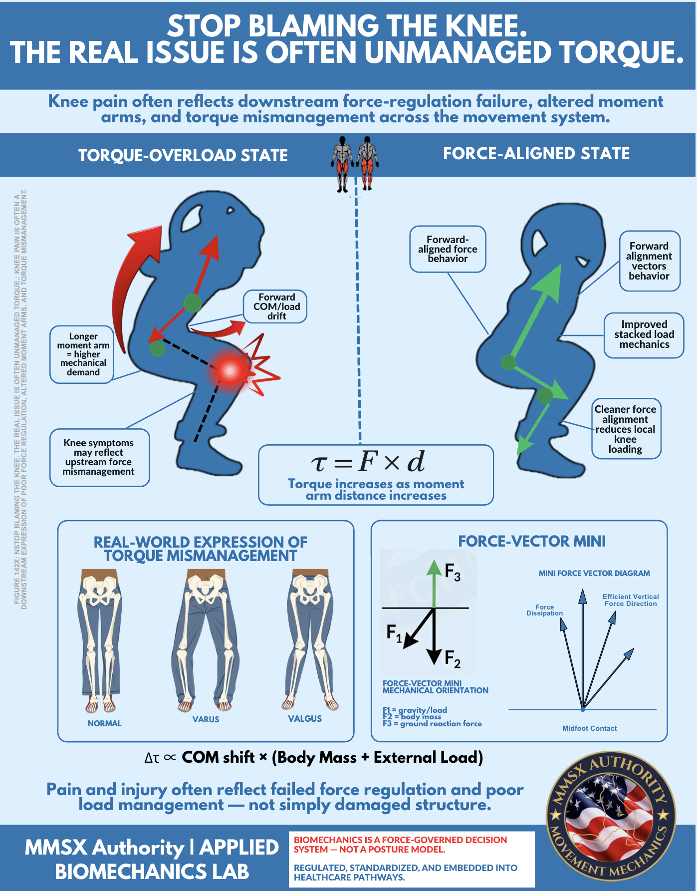
Figure 142X. Stop Blaming the Knee: The Real Issue Is Often Unmanaged Torque.
MMSx Authority Applied Biomechanics Lab. Left panel: Torque-overload state — forward COM/load drift lengthens
moment arm (d), amplifying torque (τ) at the knee. Red arrows indicate inefficient force vectors.
Right panel: Force-aligned state — improved segmental stacking, cleaner force alignment, reduced local knee loading.
Centre equation: τ = F × d — torque increases as moment arm distance increases, independent of change in applied force.
Lower panel: Normal, Varus, and Valgus pelvis/femur relationships with force-vector mini diagram.
Footnote: Δτ ∝ COM shift × (Body Mass + External Load).
Knee pain and injury often reflect failed force regulation and poor load management — not simply damaged structure.
Section 01 — Introduction
Why the Pain Site Is Not Always the Error Site
🏫 Opening Argument — Professor's Framing
Most knee-focused conversations begin too late in the chain. They begin at the pain site. And that is the first mistake. Pain is an output, not an input. It is the final visible expression of a mechanical story that — in many loaded movement contexts — started several joints away, several repetitions ago, or in a different phase of the movement altogether.
A more precise mechanical question — the question professionals should be trained to ask first — is: What changed in force behaviour before the knee became overloaded? This module teaches that question. Not as theory, but as applied clinical biomechanics that changes how you observe, assess, prescribe, and rehabilitate.
When the body moves under load, joint stress is not determined only by anatomy. It is shaped by where the centre of mass is travelling, how far the load sits from the joint axis, how well segments are stacked, how efficiently force is transferred into and out of the ground, and how successfully proximal and distal segments regulate torque. These are not separate considerations — they are one integrated mechanical system.
The knee sits between the foot-ankle complex and the hip-pelvis-trunk complex. Because of that anatomical position, it often becomes the joint where upstream and downstream inefficiencies collide and become symptomatic. A clinician who begins their assessment at the knee has already missed the beginning of the story. The tissue at the knee is the final common pathway — not the origin of the script.
The knee is often not the creator of the error. It is the receiver of the unresolved mechanical consequence.
🎯
Why a painful knee may reflect
Poor foot-ground interaction · Unstable frontal-plane control · Trunk drift · Hip control deficits · Altered deceleration strategy · External-load placement that lengthens the effective moment arm
⚖️
What shapes joint stress
COM trajectory · Perpendicular distance (d) from force line to joint axis · Segmental stacking quality · Efficiency of force transfer at ground contact · Proximal and distal torque regulation capacity
🔗
The Knee's Anatomical Reality
Positioned between two major control systems. It has limited intrinsic force-generation capacity in the frontal or transverse planes. It inherits what the hip and foot-ankle complex fail to regulate. That is not a weakness — it is a biomechanical truth that demands system-level assessment.
📍
The Educational Shift Required
From: "What is wrong with the knee?" To: "What force was not regulated, what torque was amplified, what moment arm became longer, what vector drifted, and which structure ended up paying for that failure?"
Section 02 — Decoding Figure 142X
What the Infographic Is Really Teaching
❌ Torque-Overload State
Forward COM Drift — Longer Moment Arm — Higher Local Demand
Body or load drifts forward of efficient line
Effective moment arm (d) becomes longer
Force line behaves less efficiently — vectors scatter
Local mechanical demand at knee rises
Hip contribution reduces as trunk loses control
Knee becomes a common site of symptom expression
Red arrows in figure: diverging, inefficient vectors
Glowing symptom point at knee = downstream expression site
✓ Force-Aligned State
Cleaner COM Organisation — Efficient Vectors — Shared Load
Load pathway organised closer to efficient vertical
COM better positioned relative to joint axes
Joint stacking improved — each segment shares demand
Vectors travel more efficiently through the system
Local knee loading reduced — torque better regulated globally
Critical framing: The infographic does not say one silhouette is "perfect posture" and the other is "bad posture." Posture is not the concept. Force behaviour is. The same body in two different mechanical organisations produces two different torque environments — and two different injury risk profiles. Mechanics, not aesthetics.
Section 03 — The Central Equation
Torque, Moment Arms, and Why They Matter
The Governing Equation of Knee Loading
τ=F×d
τ = Torque (rotational force demand at the joint, N·m)F = Applied force (N) — bodyweight + external loadd = Perpendicular distance from force line to joint axis (m)
If force stays constant and distance increases, torque increases — without any change in load. Geometry drives pathology.
Figure 1Torque Amplification Curve With Increasing Moment Arm Distance
Figure 1. Torque amplification as moment arm distance increases, at three loading levels. The slope of each curve steepens at larger d values — demonstrating that under heavy external load (red), even a modest increase in moment arm distance produces disproportionately large increases in local joint torque. This is why subtle forward trunk drift in a loaded squat is mechanically very different from subtle forward drift without load.
The τ = F × d equation is deceptively simple. Its clinical implications are not. In practical movement, the moment arm distance (d) is not fixed — it changes continuously as segments move relative to each other and relative to external loads. A forward trunk drift of 5° does not seem dramatic visually. But if it shifts the effective moment arm at the knee from 0.08m to 0.14m under a 100kg system load, the resulting torque increases by 75% — with no change in applied force.
This is why subtle changes can create large differences in perceived effort, tissue stress, and symptom behaviour. The eye sees a small postural deviation. The joint experiences a major mechanical load escalation. This gap between visual appearance and mechanical reality is precisely why posture-only observation is an insufficient assessment framework.
Figure 2COM Shift vs Estimated Local Knee Torque Demand
Figure 2. Conceptual relationship between anterior COM shift and estimated local knee torque demand at three loading conditions. A 6cm anterior COM shift in an unloaded squat may remain below symptom threshold. The identical 6cm shift under barbell load may cross it — explaining why patients report symptoms only under load, even with identical movement patterns when unloaded. COM shift interacts multiplicatively with load context.
The COM Amplification Equation
Δτ∝COM shift×(Body Mass + External Load)
Once total system mass is managed under load, even modest COM displacement can amplify torque demand proportionally to both body mass and any additional external load.
COM shift is not automatically pathological. Uncontrolled COM shift under insufficient regulation is the problem. That distinction separates mechanical interpretation from simplistic postural blame.
Section 04 — Centre of Mass & Load Amplification
COM Shift as a Load Amplifier — What the Equation Is Actually Saying
Figure 3Force-Path Comparison: Clean Vertical Transfer vs Forward Drift
Figure 3. Left: Force-aligned state — efficient near-vertical force path, short moment arm (d), low local knee torque demand. Right: Torque-overload state — forward COM drift creates a longer moment arm from the load's line of action to the knee joint axis, amplifying torque demand at the knee (τ = F × d) with identical applied force. The dashed lines illustrate the perpendicular distance (d) that determines torque magnitude.
Figure 4. Segment stacking and joint demand redistribution across three sagittal alignment states. As forward drift increases, hip contribution falls (hip moves behind the moment arm), knee demand elevates disproportionately, and spinal demand increases. Bar height below each silhouette indicates estimated relative joint demand. Same movement, same load — radically different demand distribution based solely on alignment geometry.
```
Section 05 — The Downstream Victim
Why the Knee Often Becomes the Downstream Victim
Figure 8Symptom Site vs Mechanical Error Site — The Body Chain Disconnect
Figure 8. The disconnect between mechanical error sites and symptom expression site in the kinematic chain. The knee (highlighted, centre) is flanked by upstream and downstream contributors. In many clinical presentations, the mechanical errors originate elsewhere — yet the knee, as the junction joint, accumulates and expresses the unresolved force consequences as pain, swelling, or functional limitation.
Figure 10Tissue Capacity vs Task Demand — The Symptom Emergence Model
Figure 10. The capacity-demand model of knee symptom emergence. Tissue/system capacity declines progressively with load accumulation, fatigue, or mechanical drift. Task demand rises as repetitions increase or alignment deteriorates. Symptoms emerge not at a fixed threshold, but at the point of intersection — where demand exceeds regulatory capacity. This model explains why many knee symptoms emerge late in a session, under speed, or under load: not because new damage occurred, but because the demand-capacity gap inverted.
Section 06 — Dynamic Force Distribution Patterns
Varus and Valgus Are Not Just Visual Shapes — They Are Force-Distribution States
Figure 5Frontal-Plane Loading Spectrum — Neutral to Dynamic Valgus to Dynamic Varus
Figure 5. Frontal-plane loading spectrum: neutral, dynamic valgus, and dynamic varus. Arrows indicate force vector direction and load distribution. Valgus (centre) represents hip adduction/internal rotation bias driving medial loading — creating an environment of ACL, MCL, and patellofemoral overloading. Varus (right) represents lateral dominance and reduced medial load acceptance — associated with IT band, lateral compartment, and degenerative patterns. Neither is purely a visual category: both are force-distribution states.
```
🏫 The Advanced Clinical Question
The real question is not "does valgus exist?" The real question is: How much valgus, under what speed, under what load, at what point in the movement, with what control, and with what symptom response?
That is the far more precise biomechanical question. Professionals who stop at "I can see valgus" have not yet asked the mechanical question. They have only performed a visual observation. Mechanical interpretation requires understanding what force distribution pattern that valgus represents, and whether that distribution exceeds the tissue's regulatory and tolerance capacity.
Section 07 — Force-Vector Logic
Force Vectors Matter More Than Static Posture Narratives
Figure 6Ground Contact and Force-Vector Organisation
Figure 6. Ground contact force-vector organisation across three foot patterns. Left: centred midfoot contact — GRF travels efficiently upward, balanced medial-lateral load. Centre: medial arch collapse — GRF deviates medially, increasing tibial internal rotation torque, feeding knee valgus and medial compartment overload. Right: lateral supination bias — GRF deviates laterally, increasing tibial external rotation torque and feeding IT band tension and lateral compartment loading patterns.
```
Figure 7Load-Sharing Radar: Torque-Overload Strategy vs Force-Aligned Strategy
Figure 7. Radar chart comparing load-sharing profiles between a torque-overload movement strategy (red) and a force-aligned strategy (green). Force-aligned movement distributes demand more evenly across ankle, knee, hip, trunk control, frontal-plane stability, and rotational control — producing smaller local peaks at any single joint. Torque-overload patterns concentrate demand at the knee, elevating local stress while under-utilising available hip and trunk control capacity.
Biomechanics is not posture. It is force behaviour under load. Posture-only language often fails because it treats alignment as a frozen visual event. Movement is a constantly changing negotiation of force. Professionals need to think in terms of vector direction, segment timing, force acceptance, force redirection, torque regulation, and local versus system-level demand.
Section 08 — Applied Clinical Scenarios
Real-World Examples in Squat, Lunge, Landing, and Stair Descent
Figure 9Fatigue-Driven Mechanical Drift Across Repetitions
Figure 9. Mechanical drift parameters across a 12-repetition set as neuromuscular fatigue accumulates. COM drift (blue), knee frontal-plane deviation (red), and hip control deficit index (orange) all increase progressively from rep 1 to rep 12. The dashed lines indicate approximate symptom/injury risk thresholds. Note that significant mechanical drift may be present from rep 7–8 onward, even before the athlete reports fatigue or shows visually obvious breakdown — reinforcing velocity-based and objective monitoring over subjective effort reporting alone.
🏋️
Loaded Squat — Forward Trunk Drift Under Increasing Load
An athlete descends with progressive forward trunk drift and anterior COM migration. Depth is achieved — but the knee begins absorbing more local stress because the load path is no longer being shared efficiently between hip and trunk mechanics. The hip contribution falls as the moment arm to the load line grows. The knee inherits the unshared demand. The athlete reports no pain until set 4 or 5 — by which point cumulative torque amplification across multiple reps has exceeded the threshold of symptom expression. The error was not in the painful set. It was in the geometry of every set before it.
Mechanical error: COM drift + hip unloading → Symptom site: anterior knee
🦵
Lunge — Anterior Knee Pain in Split Stance
A client presents with anterior knee pain in the lunge position. The instinctive response is "knee over toe." But the real pattern is poor proximal control — trunk drift forward over the front foot, insufficient force acceptance through the foot, weak eccentric hip control in the descent, and poor frontal-plane regulation at the pelvis. These produce local overload at the patellofemoral joint. The cue "keep your knee back" addresses the visible symptom. The mechanical prescription addresses poor hip eccentric loading, foot stability, and trunk stiffness — which are the actual sources of the overload.
Mechanical error: proximal control deficit → Symptom site: patellofemoral joint
🦘
Landing from Jump — Force Not Attenuated Across the Chain
The knee pain does not begin because landing exists. It begins because landing force is not being attenuated and redistributed efficiently across ankle-foot, hip, and trunk systems. If the ankle does not dorsiflex adequately, the knee absorbs a greater share of the deceleration impulse. If the hip fails to flex eccentrically under load, the knee again takes an outsized share. If the trunk cannot resist forward lean, moment arm amplification occurs at the knee. The knee is not the problem. The knee is the joint that was left holding what every other segment failed to absorb.
A patient reports patellofemoral pain descending stairs. The visible complaint is the knee. The actual mechanical pattern includes trunk drift forward and laterally over the step, reduced hip eccentric contribution in the descent, asymmetrical foot loading, and poor deceleration control through the quadriceps-patella mechanism. The patella is being loaded inefficiently because the moment arm at the knee has lengthened through trunk and COM drift, and because the proximal segments have failed to share the eccentric deceleration demand. Patellofemoral contact pressure rises — not because the knee is structurally deficient, but because it is doing the work that the rest of the chain failed to perform.
A worker reports bilateral knee soreness after repeated lifting through the day. The true issue may be repeated forward load drift and cumulative moment-arm amplification — not an isolated knee tissue problem. Each lift, the load held forward of the body increases the effective moment arm at the knee. Over 200–300 repetitions in a shift, this accumulation exceeds what the tissue can regulate asymptomatically. The occupational health intervention is not knee protection — it is load-path management: coaching the load closer to the body's vertical axis, reducing trunk lean, improving hip hinge mechanics, and scheduling recovery intervals before cumulative demand exceeds capacity.
These are the mechanical assessment questions that transform a knee complaint from a local tissue problem into a system-level force interpretation. Each question moves the clinician further from the symptom site and closer to the mechanical source.
01
Where is the centre of mass moving — and is it staying within an efficient load pathway or drifting away from it under increasing speed, load, or fatigue?
02
What happens to the moment arm distance as the task progresses through its range — does it shorten or lengthen, and at what point does that geometric shift create disproportionate torque amplification?
03
Is the knee absorbing force that should have been shared — and if so, which proximal or distal segments failed to regulate their contribution at the critical moment?
04
Is the trunk helping the system manage load, or is it amplifying the problem by drifting in a direction that increases the effective moment arm at the knee?
05
Does the foot provide a stable, responsive force-transfer base — or does pronation, supination, or midfoot collapse introduce tibial torque that the knee must absorb?
06
Is the pelvis controlling frontal-plane and rotational behaviour during the task — or does Trendelenburg drop, contralateral hip hike, or pelvic rotation add transverse-plane demand at the knee?
07
Does fatigue change the vector pattern — and if so, at what repetition, time, or load does the movement strategy shift from force-aligned to torque-amplifying?
08
Does speed reveal a different mechanical strategy than slow movement — is the knee strategy at walking speed mechanically different from the strategy at running, cutting, or deceleration speed?
09
Does symptom onset correlate with a specific mechanical drift pattern — or does it appear across all movement conditions, suggesting local tissue sensitivity rather than a primary force-management deficit?
10
Is the external load (if present) placed in a position that shortens the effective moment arm — or has load placement itself increased the perpendicular distance from the force line to the knee axis, amplifying τ without any change in task demand?
Section 10 — Toward a Mechanical Model of Pain Interpretation
Pain as a Mechanical Story — System-Level Force Interpretation
Scientific Honesty — What This Module Is Not Claiming: This educational framework is a mechanical teaching model, not a universal diagnostic rule. Knee pain can also involve local tissue pathology, inflammatory behaviour, traumatic injury, degenerative change, central sensitization, post-surgical states, and non-mechanical contributors including psychosocial factors and central nervous system sensitization. Even in those cases, mechanical interpretation still matters — because tissue status and load behaviour interact continuously. But the framework on this page is a mechanical lens, not a complete clinical model.
The mechanical interpretation of knee pain does not require clinicians to abandon tissue-based or neurobiological models. It requires them to add a force-vector layer to every assessment — a layer that asks not only what is damaged, but what force produced the damage, why that force was concentrated there rather than distributed across the system, and what mechanical change would reduce the local demand that the tissue is struggling to regulate.
This is the future of serious biomechanics in clinical practice: not local blame, but system-level force interpretation. The practitioner who sees valgus and prescribes a hip strengthening protocol has made progress. The practitioner who asks why the hip is not contributing — whether it is a motor control issue, a load-path organisation issue, a foot-stability issue, or a CNS fatigue issue — is practising force-vector decision science.
That distinction — between symptom-site treatment and system-level mechanical interpretation — is the educational core of this module, and of the MMSx Authority Applied Biomechanics Lab framework.
Module 142X — Closing Statement
The knee is often where the complaint becomes visible. It is not always where the mechanical mistake began.
When pain appears at the knee, professionals should not stop at the knee. They should ask what force was not regulated, what torque was amplified, what moment arm became longer, what vector drifted, and what structure ended up paying for that failure. That is the real message of Figure 142X. Pain is often the final expression of a mechanical story that started elsewhere.
The future of serious biomechanics is not local blame. It is system-level force interpretation.